|
I'm not ready to describe exactly what MIRTH does. I have taken these pictures,
and if you know what all the components do, you might be able to guess generally
what MIRTH might do. I'm not, however, ready to just write out what it does. It's
a surprise and I don't want to give it away. I'm not even telling here what the
name, MIRTH, stands for. A smart person can figure out some of it, I'm sure. After
I've gotten my fill of MIRTH I'll come back here and totally fess up.
|
|
|
|
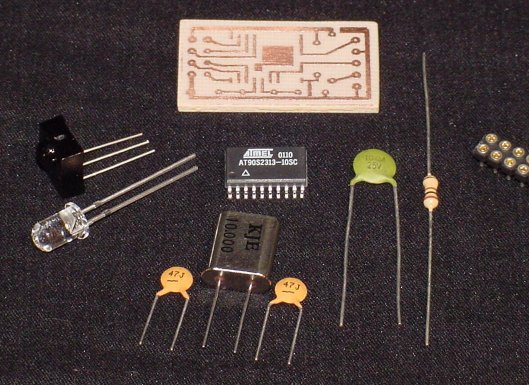
This is my first project to include SMT (surface mount technology). Most of the
components I have are non-SMT style, but MIRTH needed to be small. So, for its
brain, an Atmel 2313 AVR MCU, I went surface mount, reducing its footprint and
PCB requirements dramatically.
|
|
|
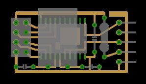
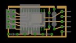
The printed circuit boards were drafted manually in Paint Shop Pro.
The layouts were applied to the copper clad board by way of
the laser-printer-iron-on technique and etched using
FeCl3 (ferric chloride - the generic stuff
you get from any electronics outlet).
|
|
|
|
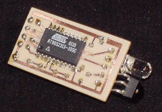
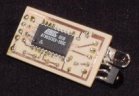
This is the CPU side of the MIRTH PCB. Dominating the tiny landscape
is the AT90S2313-10SC processor. This SMD has a pin spacing of .05 inches.
As one solders it to the PCB, it sits passively atop the traces, ever wanting
to play a joke on the assembler (me) by slipping off the tiny pads, making it
a very difficult thing to solder down. I used an aligator clip to hold it in
place, but even lining it up to be clipped down was a task. Once lined up and
pinned down, even though the pads had been pre-wetted with solder, it was
still difficult soldering those tiny pins without bridging them together.
I believe the .05 inch density of this SMD is the highest I can handle with
the tools and skills I have at the moment. Fortunately, this project
did not require running traces between the 2313's pads. I say fortunately
because I don't trust the laser printer iron-on method to reliably do that. It
can only barely handle the .02 inch pads and traces at all.
|
|
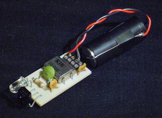
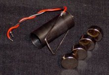
The power system also had to be small, but had to be large enough to run at
least for hours, if not for days. I went with these AG13's because I have them
on hand. Four of them give just under 6V, the max voltage rating on the 2313.
However, I do not have any data yet on how long these will drive MIRTH. I don't
have an Ampere-hours rating for the AG13's, nor a measurement of how long they
will stay above 4V, the 2313's rated minimum at 10MHz.
|
|
|
|
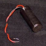
The battery consists of the afore-mentioned 4 AG13 cells, an acetal (Delrin)
housing, and paperclips as conductors. I had a chunk of 1/2 inch black acetal
round bar laying around. I bored it out to fit the AG13's, and bent paperclips
to compress the cells together within the tube. One end of the tube is closed
and has a spring that feeds out through a tiny hole; The other end is open
for easy cell replacement. Very simple, very easy, works great. And, it's black!
|
|
|
At a later time I may post the MIRTH source code. One nice thing about this
project, is that there were plenty of I/O pins left. I was easily able to
build in connections for UART RX/TX and SPI (serial programming interface).
The firmware can continue to evolve without a change in the hardware. One could
even easily use the RX, TX, and the SPI pins to give the MIRTH hardware a totally
different function; One a little less...sneaky.
|
|